Install the board support
Download the package and follow its installer guide. Select FireFLY (CH32X035F8U6, USB Serial) in Arduino IDE.
Download Arduino support ↗A tiny RISC-V brain, two dots of color, and USB built right into the PCB. Meet FireFLY.
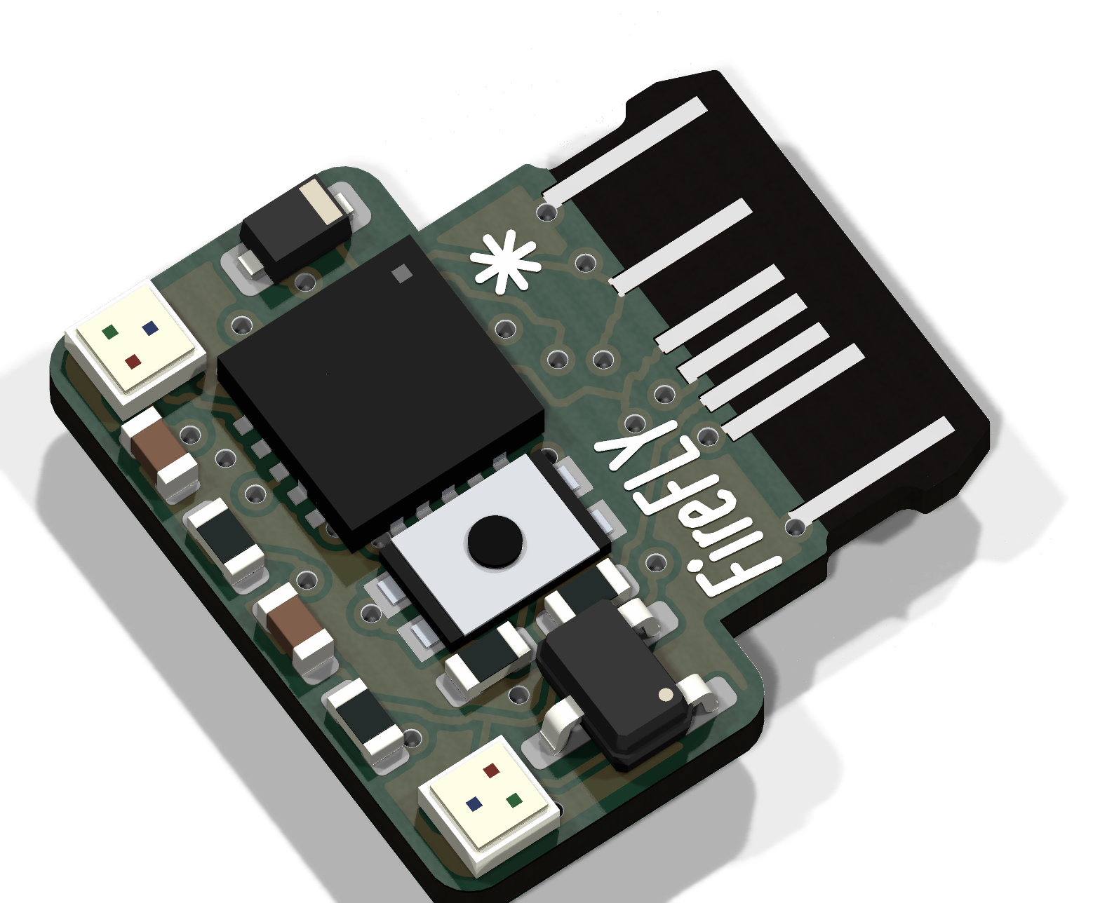
Give a small object a little personality. Read a sensor, respond to a touch, or add a pair of glowing eyes. FireFLY keeps the essentials close.
The contact tongue is part of the board. USB carries power, serial messages, and sketch uploads.
Eight solder pads and a central touch electrode keep your wiring beneath the board.
Drag to rotate. Scroll or pinch to zoom.
Flip it over to find your connections.
Loading 3D model…
The current board, exported from KiCad. Via drill holes are hidden for a cleaner preview; the manufacturing files retain them. The hardware remains a prototype.
Tap a pad to see what it does.
Shown looking directly at the underside.
BAT is an input. VCC is the supply rail. Connect battery positive to BAT and negative to GND. VCC follows USB or battery; it is not a regulated 3.3 V output. The board does not charge a cell or protect against reversed polarity or over-discharge. Use a protected single-cell pack.
Familiar Arduino sketches.
USB serial included from the start.
Download the package and follow its installer guide. Select FireFLY (CH32X035F8U6, USB Serial) in Arduino IDE.
Download Arduino support ↗Choose Tools → Upload mode → USB recovery. Hold BOOT while plugging in USB, then release it. Upload the included USBSerial example.
Switch Upload mode to USB automatic, select FireFLY’s serial port, and click Upload. The 1200-baud request reboots into the factory USB bootloader. Even an empty sketch keeps USB enabled.
void setup() {
  Serial.begin(115200);
}

void loop() {
  Serial.println("Hello, FireFLY!");
  delay(1000);
}Hello, FireFLY!
Hello, FireFLY!
▌Illustrative output. Firmware is compile-tested; USB operation still needs a physical board test.
The core starts USB CDC before setup(), services it between loop() calls and during delay(), and leaves the factory WCH bootloader intact. A 1200-baud serial close requests bootloader mode; wchisp uploads the new sketch.
If a sketch crashes, disables interrupts, or never yields, choose USB recovery, hold BOOT while reconnecting USB, and upload again. Serial.end() deliberately keeps the upload connection alive. This release uses a shared development USB identity; it must not be used in devices manufactured, redistributed, or sold. A production USB identity must be allocated separately.
D0–D4 are the five external GPIOs. A0 maps to D1 / PA6; A1 maps to D2 / PB0; A2 maps to the central touch electrode / PB1. LED_LEFT is PB11 and LED_RIGHT is PA4. The LEDs need an addressable-LED protocol, not digitalWrite().
USB D−/D+ are reserved. The underside does not expose a complete hardware SPI or I²C pin set, so these buses are not enabled by default. PA3 analog behavior depends on silicon revision and is not assigned an analog alias.
Core, installer, USB upload support, and example sketches.
GUIDE / PDFA visual reference for pads, power, and programming.
HARDWARE / PDFUSB, microcontroller, LEDs, power selection, and touch.
Prototype, with progress to share. The hardware is not production-validated. USB connector fit/finish and the selected LED land pattern still need confirmation. The 10 mm outline variant is for quotations only; FireFLY’s actual board is 9.5 mm.